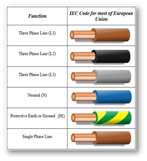
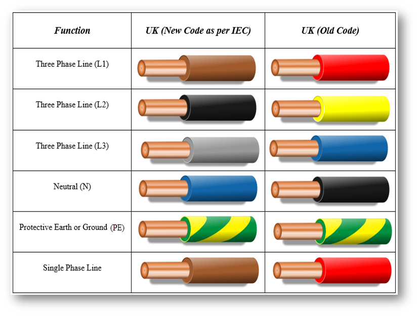
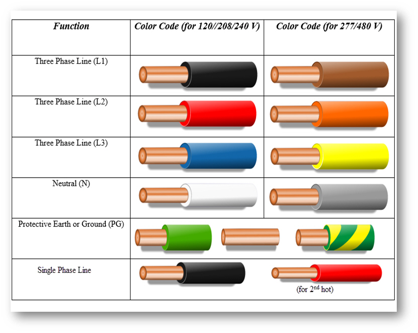
3-Phase Wiring, Colors, and Configurations

LocationL1 [R]L2 [S]L3 [T]NeutralGround/
Earth
Australia
(Note 1)
RED or
BRN
WHTDK BLU or
GRY
BLKGRN/YEL
CanadaREDBLKBLUWHT or
GRY
GRN or
GRN/YEL
Canada
(isolated)
ORGBRNYELWHT or
GRY
GRN or
GRN/YEL
European
(older)
REDYELBLUBLKGRN/YEL
European
(IEC)
BRNBLKGRYBLUGRN/YEL
Hong Kong
(pre 2009)
REDYELBLUBLKGRN/YEL
IndiaREDYELBLUBLKGRN or
GRN/YEL
Kazakhstan
(pre 2009)
YELGRNREDLT BLUGRN/YEL
MalaysiaREDYELBLUBLKGRN/YEL
New Zealand
(Note 1)
RED or
BRN
WHTDK BLU or
GRY
BLKGRN/YEL
Norway
(pre 2000)
BLKWHT or
GRY
BRNBLUYEL or
YEL/GRN
Russia
(pre 2009)
YELGRNREDLT BLUGRN/YEL
Singapore
(pre 2011)
REDYELBLUBLKGRN/YEL
South AfricaREDYELBLUBLKGRN/YEL
UK
(pre 2006)
REDYELBLUBLKGRN/YEL
Ukraine
(pre 2009)
YELGRNREDLT BLUGRN/YEL
USA
(120/240V
high leg)
(Note 2)
BLKORGRED or
BLU
GRY or
WHT
GRN (only)
USA
(480V Delta)
(Note 3)
BRNORGYELGRY or
WHT
GRN (only)
USA
(480V Wye)
(Note 3)
BRNVIOYELGRY or
WHT
GRN (only)
USA
(Std & 208V)
(Note 3)
BLKREDBLUWHT or
GRY
GRN or
GRN/YEL or
bare

Note 1: In Australia and New Zealand, active conductors can be any color except green/yellow, green, yellow, black or light blue. Yellow is no longer permitted in the 2007 revision of wiring code AS/NZS 3000. European color codes are used for all IEC or flex cables such as extension leads, appliance leads etc. and are equally permitted for use in building wiring per AS/NZS 3000:2007.

Note 2: In the USA the high leg delta (the 208V high leg) is always ORG

Note 3: In the USA phase colors have not been specified since 1975. Colors listed are common practice.

Note 4: You are allowed to run multiple conductors for phases so long as you always have all three phases represented in every conduit and every bushing that goes through metal. There is line frequency induction heating otherwise.

Overvoltage Categories

By definition, overvoltage category is a Roman numeral defining a transient overvoltage condition. Overvoltage categories I, II, III and IV are used. The term “overvoltage category” is synonymous with “impulse withstand category” used in other standards. These categories are based in statistical probability rather than the idea of physical attenuation of the transient overvoltage downstream in an installation. Nevertheless, it is understood that as power is transformed through galvanic isolation or passes through a distribution center, there is a category reduction that takes place.  

IV – Equipment of overvoltage category IV is for use at the origin of the installation. — Examples of such equipment are electricity meters and primary overcurrent protection equipment.

III – Equipment of overvoltage category III is equipment in fixed installations and for cases where the reliability and the availability of the equipment is subject to special requirements. — Examples of such equipment are switches in the fixed installation and equipment for industrial use with permanent connection to the fixed installation.

II – Equipment of overvoltage category II is energy-consuming equipment to be supplied from the fixed installation. — Examples of such equipment are appliances, portable tools and other household and similar loads.

I – Equipment of overvoltage category I is equipment for connection to circuits in which measures are taken to limit transient overvoltages to an appropriately low level. In general this means you have applied transient suppression or use regulation to limit transients to predefined levels.   * Source: IEC 60664-1 section 4.3.3.2

Electromagnetic Compatibility

Over the years, I learned EMC with high frequency / high power converters. As a result, the problems I faced were generally not the same as those of a company doing low power information technology, telecommunications or consumer equipment. This is certainly not a comprehensive list and if you can get these few things under control, you will be a long way toward making a compatible product or system.

If you care to learn some of the basics through book study or to add to your reference library, here are a few titles in my personal library:

I especially like the subtitle on the last book, “A handbook of black magic”. Often, when I am guiding a newly minted engineer through the disciplines of EMC, or even an old timer who needs help, I will mention that EMC is not really black magic, it’s actually a study of all the circuitry that was not included in the system schematics.

Here are my top five best practices:

  1. Design ground: Have you ever heard the adage in electronics 101, “Ground is ground the world ’round?” With high power or high frequency electronics this is simply not true! It does not matter if the top frequencies are LF, MF, HF or higher. If I have occasion to ask a design engineer “what impedance is ground” or “what path do the parasitic noise currents follow” and a guessing game begins, then I know there has been no consideration for designing ground.
  2. Keep low level signals separate from or orthogonal to power lines: Parasitic coupling (capacitive & inductive) between conductors is unavoidable. Whether 8 mil circuit traces under an IC chip or 6 AWG cables near a sense line, the problem is really the same. The way to mitigate in each of those cases is different but a fundamental understanding of all the coupling mechanisms is essential in any case.
  3. Don’t get mired in worries about common mode vs differential mode: Ultimately all conducted and radiated RF noise can be found at the noise source to be a difference in voltage or current across an impedance. It is when you move your reference point to the perimeter of the product or to an antenna nearby that RF noise can be communicated as common mode or differential mode.
  4. Learn how to use a spectrum analyzer/receiver: Learn the types of detectors (Avg, Pk, QP) and why they are important. Learn to diagnose the noise profile and thereby identify noise sources (more on this at another time).
  5. Learn from your mistakes: My favorite definition for wisdom is “The stuff you get immediately after you needed it most”. This is not about book learning and early in your career you are liable to make a few mistakes. In the end, each person must learn for themselves. If only we could bottle wisdom and just hand it to the next person, we could make millions.

Henry Ott’s website does a tongue-in-cheek article on “The Ten Best Ways to Maximize the Emission from Your Product.

All for now, please contact me if you have specific questions on any of these topics.

:Doug

Pollution Degrees

Pollution Degree is an Arabic numeral characterizing the expected pollution of the micro-environment. Micro-environmental conditions depend primarily on the macro-environmental conditions in which the equipment is located and in many cases the environments are identical. However, the micro-environment can be better or worse than the macro-environment where, for example, enclosures, heating, ventilation or dust influence the micro-environment.

PD1 – Pollution degree 1 – No pollution or only dry, non-conductive pollution occurs. The pollution has no influence.

PD2 – Pollution degree 2 – Only non-conductive pollution occurs except that occasionally a temporary conductivity caused by condensation is to be expected.

PD3 – Pollution degree 3 – Conductive pollution occurs or dry non-conductive pollution occurs which becomes conductive due to condensation which is to be expected.

PD4 –Pollution degree 4 – Continuous conductivity occurs due to conductive dust, rain or other wet conditions.

* Source: IEC 60664-1

Product Safety Certification – A Checklist

During the stages of product development it is a good idea to consider safety design constraints, material selection and best practices as early as possible. There is possibly nothing more costly and embarrassing as having finished a project on time and on budget only to learn that some key part of your design is not acceptable to the safety agency. Worse, are the costs and lost time in recovering from a revelation such as this. Below is a collection of the more common activities you should be prepared to do when certifying your product. ~ Doug


Obtain and familiarize yourself with the safety standard(s):

  • Identify and obtain an up-to-date copy of all applicable product safety standards.
  • With internationally harmonized standards you will discover parts of the world that implement these standards on different timelines
  • Depending on those parts of the world where you want to market your product, you may also find national differences which require additional measures for acceptance
  • Read the standard in enough detail to be familiar with those parts which are applicable to your product and the markets where you are going
  • Apply the applicable clauses of the standard during the early stages of product design
  • Itemize areas of special concern or high risk of failure when presenting your product to the safety agency for evaluation
  • Test critical high-risk areas and do not rely on computer modelling alone

Component selection:

  • Use components in safety-critical areas that are certified by an acceptable third party for the intended application
  • NRTL certified parts usually meet this requirement
  • Listed, CE Marked and CB-Certified components may require additional investigation
  • Always use components within their certified ratings
  • Always obtain “conditions of acceptability” for critical components
  • In general, military or mil-spec ratings are not acceptable
  • Custom or specially fabricated components must be assessed as early as possible
    For example, a custom molded connector housing may need to have the plastics evaluated by several tests which can add months to your schedule (Hot Wire ignition, Ball Pressure, Flammability, etc.)

Circuit isolation and spacings:

  • Be very clear about each circuit type, how it will be classified for potential hazards and its proximity to other types of circuits:Mains/Secondaries/SELV/PELV/TNV/other
  • Determine and design to required spacings (physical distances) for insulation:
    • Clearance – distance through air
    • Creepage – distance over surfaces
    • Solid insulation – thickness through insulation, voltage strength, impulse ratings, etc.
  • Understand the environmental conditions:
    • Overvoltage Category – transient spikes routinely occur on the power grid. These can propagate into a building and cause damage to equipment.
    • Pollution degree – depending on the conditions where your product will be used dirt, dust, humidity, moisture and weather can increase spacings requirements.
    • Altitude – most standards use 2,000 meters as the default. Many populated areas of the world are higher than this and clearances will have to be increased accordingly.
  • What is the voltage involved when assessing spacing requirements:
    • Is the voltage sinusoidal, direct current or a combination?
    • Are there recurrent peaks such as those produced by a switch-mode power supply?

Polymers and printed wiring boards:

  • Most plastics will require a minimum flame rating
  • If a material is in direct contact with live circuits or used as a critical insulator, the thermal rating is very important to know
  • Consider the plastic’s use: enclosure? insulator?
  • Comparative tracking index (CTI) of a material may change spacings requirements
  • Special requirements apply to the use of conformal coatings
  • Many of the same ratings apply to the laminates used in printed wiring boards

Mechanical hazards and moving parts:

  • Pinch points, crushing, sharp edges, fast moving parts, high pressure and breaking glass are just a few of the potential hazards

Sources of radiation:

Chemical hazards:

  • Caustic or corrosive substances can be damaging or hazardous which means leaks and spills must be controlled
  • Toxins and various gases can also present a hazard
  • Some chemicals can cause unexpected reactions, for example leaking battery electrolytes can react with some metals and explosive gases result

Outdoor use and immersion of products:

  • For products of this type used in North America it may be necessary to apply the requirements of UL 50 (USA) and CSA C22.2 No. 94 (Canada).
  • Other parts of the world have additional requirements found in IEC 60529 or EN 60529 for ingress protection from dirt, dust and liquids.
  • These standards have requirements for assessment of the plastics for UV exposure and of gaskets relied upon for ingress protection

Product Markings and User Documentation:

Place labels and markings on the product as intended or provide mechanical drawings drawings showing where markings will be placed. For example:

  • Manufacturer or trademark, model, country of origin
  • Electrical ratings
  • Safety warnings
  • Installation instructions & user/operating instructions will require a thorough review.

Risk Assessment:

  • Many of the latest edition UL standards, IEC standards and their national derivatives now require a formal risk assessment for all potential hazards which are not explicitly covered by the safety standard
  • This can be leveraged by an existing FMEA / FMECA process or by other means

Engineering Change Control:

  • As with the original product design, any changes to safety critical material, components or function must be approved by the safety agency

Factory audits:

  • NRTLs require at least four unannounced factory surveillance audits per year
  • You will receive four audits at each registered factory location, including locations for factories that are outsource manufacturing
  • Be prepared to show that the certified product remains compliant over time
  • A demonstration of production line safety testing will be required; this usually includes electric strength testing and earthing continuity testing
  • When you get a copy of the test report, review it; this is what the factory inspectors use to conduct their inspections

As always, if you need assistance with any aspect of safety review and testing, feel free to contact us.