
Purpose
This guideline is specifically for Protective Earth (PE) and Safety Grounding. While many types of grounding are possible, this is not the same as equipotential grounding, for the functional operation of equipment or for measurement of electrical quantities.
While the safety ground is normally not called into service for the life of the product, it must be a reliable way of keeping the equipment safe for many years of operation. In this guide, protective earthing and safety grounding is intended to provide a high quality, low impedance grounding electrode system that remains reliable in temperature extremes, high/low humidity and even in weather-exposed areas.
PE provides an electrical path for high fault currents that may otherwise cause electrical enclosures or safety extra-low voltage (SELV) circuits to become live. PE improves the clearing time of overcurrent protective devices to prevent fires and they assist surge protective devices (SPD) to limit destructive surges and voltage spikes from entering equipment. Simply stated PE conductors should be large enough and bonded well enough to protect from electric shock, fires and equipment damage.
Contents
- Purpose
- General Rules and Best Practices
- DO NOT use any of the following symbols for Protective Earth (PE) connections
- Application Notes
- Basic concepts and hardware stack-up
- Primary Protective Earth
- Secondary PE connections within an enclosure
- Other Secondary Protective Earthing (daisy chain)
- Other devices
- Printed Circuit Boards
- Enclosure covers and doors
General Rules and Best Practices
- Use
external toothed star washers or serrated fasteners between the PE conductor and the device or panel to be bonded. - Star washers may be steel or may be tempered non-ferrous-conductive type, for
example beryllium copper or phosphor bronze. Soft brass, soft copper, soft bronze, aluminumand other such metals are not allowed for locking hardware. - Compressible non-conductive washers are not allowed in the hardware stack-up (e.g. fiber or plastic).
- Use only non-compressible, metallic parts in the hardware stack-up. Plastic parts and PCB laminates are not allowed (for PCBs metallic inserts may be used).
- A locking fastener is used to mechanically secure the assembly in place and prevent parts from rotating.
- Fasteners must be of a locking type and may optionally use integral star washers if they are external tooth type.
- Non-conductive coatings such as paint, varnish, powder coat or anodize must be removed or masked before application.
- Protective Earth wires must use Green / Yellow wire which has 50/50% color coverage (one color may cover no less than 30% and no more than 70% and the other color covers the remainder). The colors may be either spiral or vertically striped, in the example to the right the middle wire is not acceptable. Alternatively, for large conductors or grounding bus bars, green/yellow
heatshrink may be applied near both ends.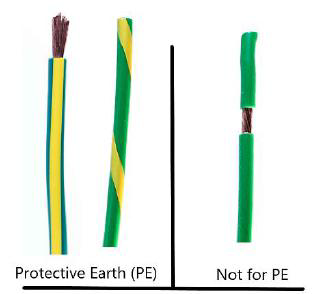
- The Protective Earth label showing the “inverted-tree-in-circle” must be used at the primary PE connection of the product and all secondary PE connections of serviceable modules or assemblies.
- The label or marking symbol must be placed in a conspicuous location near each terminal where PE bonding is required.
- This symbol may be part of a label, silkscreen or permanently embossed or stamped in the metal.
- Colors must be contrasting and not obscured by colors already present on the equipment (BLK/WHT, WHT/BLK, GRN/YEL, YEL/GRN are preferred)


- IEC 60417:5019
Protective earth; protective ground- To identify any terminal which is intended for connection to an external conductor for protection
agains telectric shock in case of afault, or the terminal of a protective earth (ground) electrode.
Note: the circle must be printed and not simply in the shape of a label.
- To identify any terminal which is intended for connection to an external conductor for protection
- IEC 60417:5019
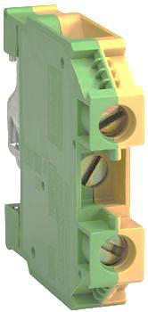
- If advantageous, PE may be included on
terminal block in which case PE markings should be provided or optionally theterminal block itself cancolored with the GRN/YEL scheme as shown.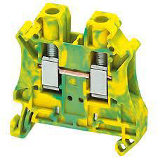
DO NOT use any of the following symbols for Protective Earth (PE) connections


- IEC 60417:5017
Earth; ground (no circle) - IEC 60417:5018
Functional earthing; functional grounding
- To identify a functional earthing (grounding) terminal, for example, of a specially designed earthing (grounding) system to avoid causing malfunction of the equipment.
- Terminal by which electrical connection is made directly to a point of a measuring or control circuit or to a screening part and which is intended to be earthed for any functional purpose other than safety.
- IEC 60417:5020
Frame or chassis- To identify the frame or chassis terminal
- IEC 60417:5021
Equipotentiality- To identify the terminals which, when connected together, bring the various parts of
an equipment or of a system to the same potential, not necessarily being the earth (ground) potential, e.g. for local bonding.
- To identify the terminals which, when connected together, bring the various parts of
- IEC 60417:5173
Signal low terminal- To indicate the signal terminal, the potential of which is closest to earth or chassis potential.
- IEC 60417:6296
LUM connection; luminaire connection- To identify the terminal for earth connection with luminaire light source terminal block and to provide information for preventing connection with other electrical equipment.
Application Notes
Explanation of proper use
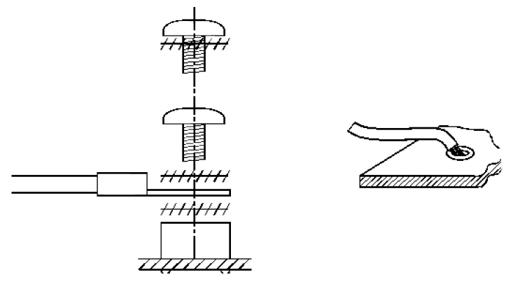
1. Basic Concepts and Hardware Stack-Up
Several combinations are possible. Examples throughout the rest of this document represent a few of these combinations.
- Chassis-stud + star + ring lug + Nyloc® nut (liquid thread locker or Nypatch® are not allowed)
- Chassis-stud + star + ring lug + star + hex nut
- Chassis-stud + star + ring lug + KEP nut
- Chassis-standoff + star + ring lug + SEM screw
- Chassis-standoff + star + ring lug + star + screw
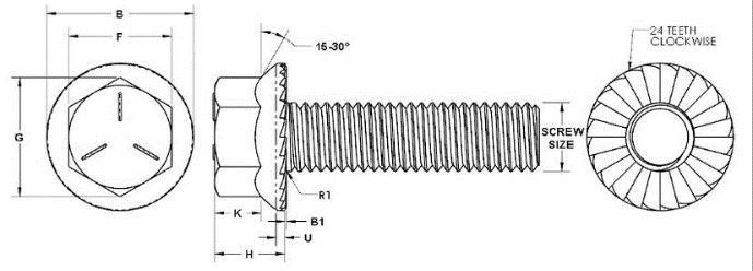
- Serrated Flange-head (special case)
High current (greater than 80 Amps) or RF (radio frequency) grounding may disallow star washers for improved conductivity. In these cases, consult with Compliance Engineering to determine
Low current grounding (less than 20 amps) with self-tapping screws may be considered if there are a minimum of two screws used and they must be “thread-forming” and not “thread-cutting” type. The minor diameter of the screw may not be less than twice the thread pitch.
All metals used for Protective Earth grounding must be galvanically compatible to avoid bi-metallic corrosion. The combined electrochemical potential must be less than 0.6 Volts. Consult with Compliance Engineering if you are unfamiliar with these concepts.
2. Primary Protective Earth
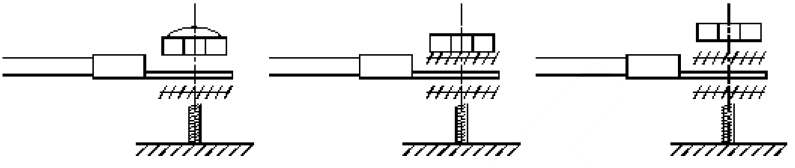
Primary Protective Earthing is a special case connection from the input power cable. It uses a single “dedicated and direct connection” to the main chassis with locking fastener. The scheme is to first place a star washer between the lug and the chassis. This is the electrical bond. Followed by one of three possible locking fasteners for mechanical securement:
- Nyloc® nut
- KEP® nut
- star washer + nut
Grounding lugs are acceptable if they are correctly bonded to the chassis. An exception is when the Primary PE connection is made on the input of a modular EMI filter. In this case, the filter itself or a secondary wire leaving the filter must have a proper protective earth bond.
For large connections (high current) such as bus bars and KCMil or MCM cables, it may be preferable to use serrated flange head bolts or nuts.
A grounding power connector may be used for Protective Earthing if the following conditions are met:
- The conductor and grounding pin & socket arrangement must be sufficient for the maximum fault current available in the enclosure.
- The grounding pin must be of the “early make” type.
- The grounding wire within the enclosure is considered the primary Protective Earth and must have a dedicated bond to the chassis.
- If other sources of fault current are greater than the connector grounding pin and wire can withstand, a secondary Protective Earthing cable must be provided to prevent burning out the connector and grounding pins.
3. Secondary PE Connections within an Enclosure
To apply a Secondary PE wire for internal connections at the same point as the Primary PE connection. For this example, it is necessary that the Primary PE wire
Use of bus bars for protective earthing is acceptable for multiple secondary PE wires. The bar itself must be correctly earthed and securely mounted to the enclosure. The bus bar must be of adequate size to handle the largest fault current available. A minimum cross-section is 2,000 Amps per square inch of a cross section for plated copper bars. The PE Label is strongly recommended in this case.
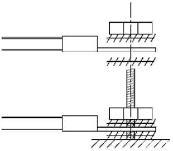
4. Other Secondary Protective Earthing (Daisy Chain)
All connections using a “daisy chain” scheme must be ultimately referenced to the Primary PE connection. There may be up to two lugs per stud. Two possible methods are shown for connecting branch circuits using a locking nut and a screw with locking star. The star washer may be integral to the screw (SEM screw) but of the external tooth type. It is allowable to daisy chain PE wires and branch PE circuits may have reduced wire sizes but must be able to carry the maximum fault current along the chain for all the devices being bonded. Note: the two-lug connection does not have a star washer between the lugs.
5. Other Devices
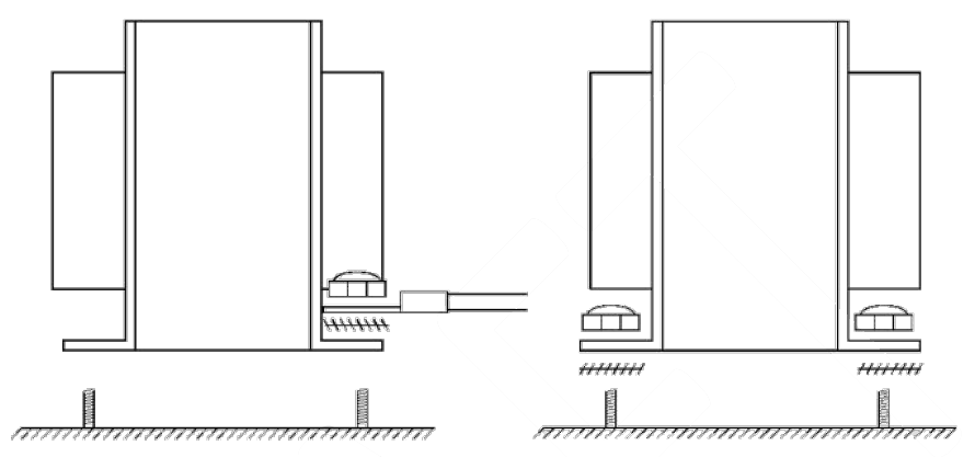
Other devices with grounded bodies such as transformers, inductors, heatsinks, guards, connector enclosures, etc. and requiring PE must have:
- star washers placed between the mounting bracket and the main chassis at every mounting point and a lock nut securing the bracket, or a PE wire applied to the device with proper hardware at a single mounting screw.
- an internal device may be bonded with external screws and star washers.
- Note: many devices have non-conductive paint, varnish or powder coat. All such coatings must be removed in the immediate area to expose the base metal for the star washer to engage.
6. Printed Circuit Boards
PE bonding of PCBs must use solderable swage nuts that are
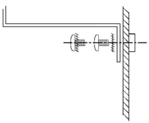
7. Enclosure Covers and Doors
External covers that require PE bonding shall use star washers between the head of the fastener and the metal cover. Nonconductive coatings must be masked out in the areas of contact between the metal pieces. A star washer between the two metal plates is not advised.
In this scheme, the grounding of the cover is achieved by using a press-in fastener which displaces metal to make a secure electrical connection and the screw is the fault current conductor. The star washer under the head of the screw serves to ground the screw head to the metal cover as well as provide mechanical securement. This usage creates a clean microenvironment in the connection areas that
Optionally, external covers may have a PE wire bonded to the chassis and directly applied to the metal cover itself.
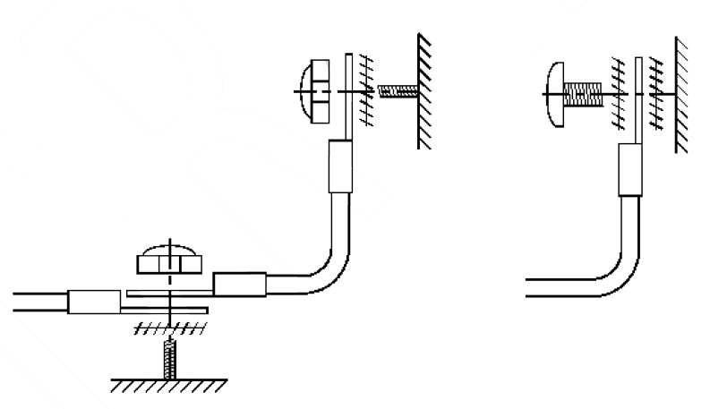
Hinged doors and panels with a wire between the main chassis and the door must be arranged so that the wire or ground strap cannot become pinched or cut in the door jamb. Frequently this can be a result of using the “horseshoe bend” across the opening. An alternative method is to use a “Z bend”. The following example assumes the steel strap is correctly bonded to earth on the right and the door is in the left. All landing points for the star washer + lug arrangement have exposed bare metal or conductive coatings. Non-conductive paints or powder coat are not allowed.
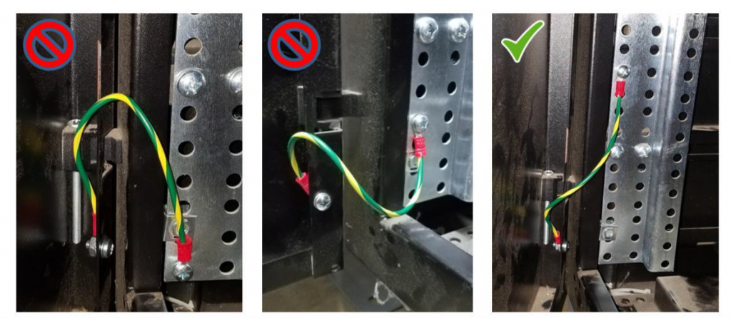
Note 1: Never on the door hinge alone for Protective Earth grounding. Exception: Approved electrical grounding hinge (EGH) with appropriate 3rd party certifications.
Note 2: Protective Earth wires used in this manner are not suitable as RF grounding and for EMI considerations.